
Talk to a product expert
Why Most Engineering Drawing AI Tools Fail at GD&T


This article was prepared by Jim Beary as part of his work with SAE International. Article and image © SAE International.
I’ve spent a couple of decades using and teaching geometric dimensioning and tolerancing (GD&T), and one of the first things I tell every class is that we’re not discussing a pile of decorative symbols. GD&T is a precise engineering language developed over several decades, used to communicate allowable variation, convey product function, and control risk.
The catch is that a GD&T symbol doesn’t live in isolation. Its meaning depends on the features being controlled, the datum reference frame, the material condition modifiers, the tolerance value, and the functional relationships across the product definition.
When you read a 2D drawing or a GD&T annotated MBD 3D model, you’re interpreting part of a functional system. That context, which is both broad and deep, is what some AI tools handle in pieces, while other tools miss completely or worse, generate GD&T symbols and claims that don’t remotely align with the Y14.5 standard.
So if you’re sizing up a tool that claims to read engineering drawings, let me save you some trouble. The question is not whether it uses AI, because many tools now claim some form of AI capability. The better question is whether the tool can evaluate functional relationships and assembly conditions across the full product definition, or whether it will green-flag a confident, polished mistake.
And if you want to stand behind the quality of your design, the product, and your reputation as an engineer, to say nothing about professional liability, then don’t trust any tool on its own without due diligence. When in doubt, share your designs with a colleague who knows GD&T — or better yet, invest in professional development so you can understand the system yourself.
GD&T is a system and a language, not a list of symbols
Let me back up and define what we’re actually talking about. GD&T is a symbolic language used globally to communicate allowable variation in part features and the relationships between those features so parts and assemblies can fit, function, and be verified as intended. It doesn’t simply tell a manufacturer how precise each feature must be. It communicates what variation is allowed, how features relate to datums and other features, and how requirements should be interpreted under the applicable standard.
ASME describes Y14.5 as the authoritative guideline for the design language of GD&T, and states that it establishes symbols, rules, definitions, requirements, defaults, and recommended practices for stating and interpreting GD&T and related requirements on drawings, models defined in digital data files, and related documents.
One foundational principle is that datum reference frames should be established based on the function of the part in the assembly with its mating parts. In plain terms, you look at how the parts fit together, you identify the functional contacting, orienting, and locating features, you understand the intended sequence where applicable, and you identify those datum features with labels such as A, B, and C.
Here is an example below:
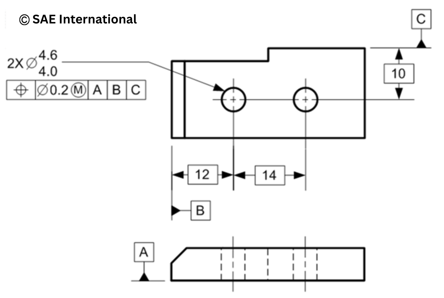
A product’s function is the number one driver here, but manufacturability is right behind it. You can design almost anything these days, but the question I always come back to is whether you can actually make it, verify it, assemble it, and do all of that at an acceptable production cost. That’s why I tell engineers to think about datum features and datum reference frames as early as they can. When you intentionally plan and design how a part locates in the assembly, you are controlling variation on purpose instead of getting an ugly and expensive surprise later.
Can a GD&T scheme be standards-compliant and still be wrong?
Yes, it definitely can. More precisely, a GD&T scheme can use valid symbols and follow the syntax of Y14.5 while still making poor functional choices. That’s an important distinction to keep in mind.
Let me give you an example I use in training. Picture a small bracket that supports a freezer door. Before anyone can build or inspect the part well, the drawing has to communicate how the part is intended to locate and function in the assembly. A datum reference frame provides the origin and orientation for related geometric requirements when those datums are referenced. It is not a casual starting point, but the framework for interpretation.
Now let’s say our bracket gets a clean-looking datum reference frame and sails through an AI-powered standards check. The trouble, which we’ll (hopefully) learn later, is that the datum scheme does not reflect how the bracket actually functions. Somebody saw a central hole and assumed that was a locating feature, when instead it was a clearance hole for a fastener. So the part gets controlled relative to a feature it doesn’t actually locate relative to in use. It may pass a syntax check on paper, but it can still sit out of position when installed. The callouts may be technically recognizable. Functionally, the design intent is wrong.
That problem then shows up downstream, which is where it always gets expensive. The bracket can float, the freezer door can end up misaligned, scrap and rework can climb, and craftsmanship suffers. More to the point, what homeowner or restaurant is going to buy a freezer with a door that looks misaligned? Next time, they’ll likely choose your competitor.
Maybe an AI tool led us down this path, but for many years that wasn’t the case. People have unfortunately been making these mistakes for several decades without software involved. That’s exactly why ASME Y14 compliant GD&T is the right lens for judging engineering AI. It exposes the gap between recognizing symbols and understanding product definition.
What AI for GD&T can do today, and where it falls short
Let me be honest about where these tools can help, because this is absolutely not intended to be an anti-AI piece. In fact, I use AI multiple times daily and value the productivity enhancements it enables.
If a tool is configured correctly, trained against reliable information, and checked by someone who knows the applicable standard, it can help with a first-pass review. It may identify annotations, extract GD&T callouts, compare symbols and structures against predefined rules, and flag items that appear plainly incorrect under ASME Y14.5 or ISO GPS. That can save time.
Where these scenarios tend to fall apart is when people ask AI to make the engineering judgment for them. Many current tools do not reliably determine whether datum references match how the part actually functions and assembles or how variation moves through the assembly. A tool may recognize a valid-looking feature control frame and still miss the fact that the datum strategy does not represent function.
Not long ago, I asked one of the big AI assistants to build me a simple GD&T chart per Y14.5, and it couldn’t even get the symbols right. That matters because the input side of this problem worries me as much as the review side. There’s a flood of incorrect AI-generated GD&T being posted right now, full of wrong symbols and claims that it meets the standard, created by those who have minimal or zero knowledge of the Y14.5 standard. Feed that bad information into an automated AI tool and you risk reinforcing misinformation. A trustworthy tool must distinguish correct from incorrect, and many tools are not there yet.
Why almost-correct GD&T is the most dangerous kind
Here is something that took me years to fully appreciate. Obviously wrong engineering work often gets caught by people who know better. The more dangerous work is the almost-correct version that looks polished enough to slip past a quick review.
This becomes even more important as teams move from 2D drawings toward model-based definition supporting a model-based enterprise. GD&T that used to sit on a drawing for a person to read can now be embedded directly in a 3D model as product manufacturing information. Downstream systems can automatically import and consume that data for manufacturing, inspection, quality, supplier review, and other workflows. If the semantic connection is broken or the requirement is wrong, the mistake can move faster and farther than it did in a drawing-only environment.
One wrong datum reference or incomplete requirement can create significant negative downstream consequences. It can stop a CNC process, cause inspection software to fail, create confusion for a supplier, or drive expensive scrap and rework. The point is not that every GD&T mistake creates a catastrophe. The point is that incomplete or incorrect product definition creates risk, and modern digital workflows can significantly amplify that risk.
At the far end of the spectrum, incomplete or wrong definitions can contribute to serious failures. I earned my GD&T certification while working on spinal implants, and let me tell you, a failure involving someone’s spine is not like a freezer door that sits a little off. If hardware loosens, shifts, fractures, or does not function as intended, the consequence may be another surgery, permanent injury, or worse. In regulated medical-device environments, those kinds of failures can also trigger formal complaint, investigation, and reporting obligations. That is why “almost right” is not nearly good enough.
I tell my students to imagine standing in a courtroom defending every symbol on their design, because one day someone may have to. That’s the level of rigor and diligence this work deserves.
The one test to run on any AI drawing tool
If you want to know whether an AI for GD&T tool can really help, here is the test I would run, and it’s similar to what I would do with a junior engineer.
Take a part you know well, ideally with both a 2D drawing and a 3D model if those are available. Start with a version you know contains errors. Watch whether the tool catches the low-hanging fruit like incorrect or missing symbols, incomplete feature control frames, missing datum references where they are required, improper or questionable datum reference sequences, and missing controls needed to relate important features back to the datum reference frame.
If it can’t flag those basic issues, I would stop right there.
If it passes that first screen, go further and try to break it. Feed it a known-good example and see whether it agrees for the right reasons. Feed it another example with a deliberate error, such as a wrong symbol, missing modifier, missing control, or questionable datum strategy, and see whether it challenges you. You are debugging it from both directions.
The first test is whether it can recognize and apply the standard. The harder test, and the one that matters more, is whether it can help you evaluate whether the designer made the right functional choices in the first place.
What should never ship without a Y14.5-literate human
Let me leave you with the rule I live by when it comes to AI for GD&T:
“Trust, but verify.”
Anything that matters needs a set of eyes and a mind that genuinely knows the standard. I don’t say that lightly. You can earn a four-year engineering degree with a 4.0 GPA and see GD&T only in passing, if you see it at all. The cases that worry me most are the engineer who is confident that they know GD&T but don’t, and the team that buys into a polished AI demo and assumes the tool will handle the thinking for them.
The best path forward, even in a world of engineering AI, is to get the right people and teams in the room early. Design, manufacturing, quality, and dimensional metrology working together is not a nice-to-have. It is how you develop a complete, robust product definition. The old habit of designing in a silo and throwing the problem over the wall for someone else to solve manufacturing and quality issues is a recipe for failure, and it won’t keep companies competitive for long.
The next time a vendor tells you their tool reads drawings, take the phrase “it uses AI” with a big grain of salt. Don’t trust the demo by itself. Try your own examples, including a mix of correct and incorrect drawings or models, and watch what the tool actually does with them.
Engineers, by training and often by nature, have a healthy dose of rigor and discernment. That’s a very good thing. We should embrace useful technology, but we also need to stay technically honest. The more tempting it becomes to let AI tools do the thinking and judging for us, the more important it becomes for engineers to understand the intent behind their designs. That includes understanding the fundamentals of GD&T.
About the author
Jim Beary is the GD&T Technical Sales Director, subject matter expert, and instructor for SAE International, and is active on the following ASME committees:
- Y14.43 – Dimensioning and Tolerancing Principles for Gages and Fixtures Committee – Vice Chair
- Y14.5.2 – Certification of GD&T Professionals Committee – Vice Chair
- Y14.5 – Dimensioning and Tolerancing Committee – Member
- AED Assembly Level Tolerancing Project Team – Member
- Model Based Enterprise Support Group – Member
He’s trained thousands of professionals in GD&T globally and mentored more than 25 professionals to achieve their ASME GD&T Professional certifications. Follow Jim’s GD&T commentary on LinkedIn.



About the author
Jim Beary is the GD&T Technical Sales Director, subject matter expert, and instructor for SAE International. He’s trained thousands of professionals in GD&T globally and mentored more than 25 professionals to achieve their ASME GD&T Professional certifications.

