
The Engineering Leader’s Guide to Generative Design Tools
A practical guide to the best generative design tools in 2026 — covering optimization-based tools, text-to-CAD, and what's actually worth using for mechanical engineers.


The Shift: From Optimization to Creation
Generative design now means two different things. It is critical to distinguish between them to understand where they fit in your workflow:
- Optimization-Based Generative Design: Uses simulation and optimization (often topology optimization) to remove material or create lattice structures based on loads and constraints.
- Generative AI for CAD: Uses models trained on geometry and engineering data to help create or edit CAD from text, sketches, or guided prompts.
Both can speed up design work, but they solve different jobs. Optimization tools help you refine and lightweight parts after constraints are known. Generative AI tools help you explore concepts and automate repetitive CAD tasks, though they currently require careful validation.
Here are the top tools defining both categories.
Category 1: Optimization-Based Generative DesignOptimization-Based Generative Design
Best for: Light-weighting, structural optimization, and complex additive manufacturing parts.
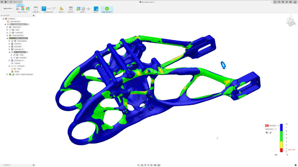
1. Autodesk Fusion Generative Design
What it is: A cloud-based solver that uses AI and computing power to generate many design alternatives based on user-defined constraints (materials, safety factors) and manufacturing methods.
Key Features:
- Manufacturing Constraints: Allows users to filter outcomes by production method (e.g., additive, 3-axis milling, die casting).
- Outcome Comparison: Groups designs by visual similarity, helping engineers filter and compare trade-offs between mass and cost.
Output Type: Editable T-Spline solid (can be converted to B-Rep).
Best for: Teams who need to rapidly explore trade-offs between different manufacturing methods for a single part.
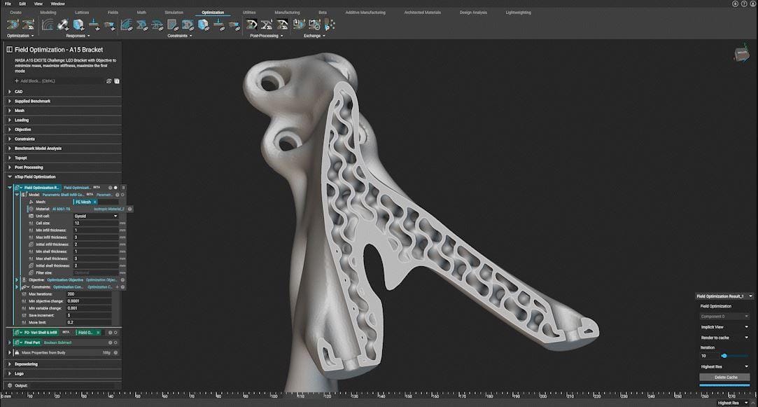
2. nTop (formerly nTopology)
What it is: A platform built on "Implicit Modeling" that handles highly complex geometry, such as lattices and gyroids, which often crash traditional CAD kernel.
Key Features:
- Field-Driven Design: Uses simulation or test data (thermal maps, stress fields) to drive geometry density and thickness directly.
- Reusable Workflows: Allows engineers to package complex logic into reusable blocks.
Output Type: Implicit geometry (convertible to mesh/STEP for specific workflows).
Best for: Aerospace and medical applications requiring lattice structures, thermal management, or complex lightweighting.
3. Siemens NX Generative Engineering
What it is: An enterprise-grade solution enabling generative workflows within a Tier-1 CAD environment.
Key Features:
- Convergent Modeling: Allows engineers to mix and operate on faceted data (mesh) and precise B-Rep data (solids) in the same model without conversion errors.
- Integrated Simulation: Runs optimization studies directly inside the native NX environment.
Output Type: Convergent Body (hybrid mesh/solid).
Best for: Large enterprises already in the Siemens ecosystem who need a seamless workflow between generative concepts and final production CAD.
4. MSC Apex Generative Design
What it is: A tool focused on generating additive-manufacturable structures with a specific emphasis on smoothing the transition from "rough" optimization results to clean geometry.
Key Features:
- Smart Smoothing: Automates the "re-surfacing" step, converting jagged topology optimization meshes into smoother surfaces.
- Stress-Based Optimization: Solvers are tuned to minimize stress concentrations automatically.
Output Type: Smooth NURBS-like surfaces / CAD-ready geometry.
Best for: Additive manufacturing teams looking to reduce the manual time spent reconstructing geometry from topology optimization results.
5. PTC Creo Generative Design Extension (GDX)
What it is: A cloud-powered extension for Creo that runs optimization studies in parallel to the native CAD environment using the Ansys solver engine.
Key Features:
- Native Integration: Optimization results are returned directly into the Creo environment.
- B-Rep Reconstruction: It attempts to reconstruct the optimized shape as editable geometry rather than just a static mesh.
Output Type: Tessellated mesh or Reconstructed B-Rep body (General Boundary Representation, not a parametric feature tree).
Best for: Creo users who want to add generative capabilities without leaving their native CAD interface.
Category 2: Generative AI for CADGenerative AI for CAD
Best for: Rapid conceptualization, scan-to-CAD, and reverse engineering.
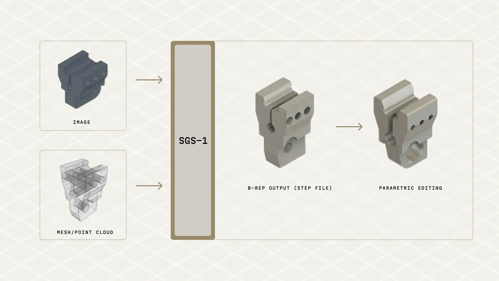
6. Spectral Labs (SGS-1)
What it is: Spectral Labs is building the "ChatGPT for CAD." Their model (SGS-1) allows engineers to input simple prompts—like a text description, a rough 2D sketch, or a 3D mesh scan—and generates fully editable, parametric 3D CAD files. Unlike topology optimization (which subtracts material), this uses generative AI to create new geometry from scratch.
Key Takeaway:A glimpse into the future of "Prompt-to-CAD" workflows that could drastically speed up initial modeling.
7. GenCAD-3D
What it is: A multimodal generative AI framework (developed at MIT) that solves the "Scan-to-CAD" bottleneck. Unlike tools that just fit surfaces to a scan, it uses AI to infer the original "recipe" (parametric feature tree) needed to build the part from a point cloud or mesh.
Key Features:
- Scan-to-Program: Converts unstructured 3D scans (point clouds) into sequential, editable CAD operations (Sketch > Extrude > Fillet).
- Latent Space Alignment: Uses contrastive learning to understand the relationship between "rough" geometric data and "exact" CAD history.
Output Type: Editable Feature Tree / CAD Program (re-executable script).
Best for: MRO (Maintenance, Repair, and Operations) teams and reverse engineering workflows where the original CAD is lost.
8. Zoo
What it is: A developer-first platform building a modern geometry engine (modeling kernel) accessible via API and AI.
Key Features:
- Text-to-CAD: A machine learning API that generates B-Rep CAD models from text prompts.
- KittyCAD Language (KCL): A code-based design language that allows for diffing, merging, and version control of hardware designs.
Output Type: B-Rep (STEP files).
Best for: Software-savvy mechanical engineers ("Design Engineers") and developers building custom design tools.
9. CADScribe
What it is: A browser-based generative AI tool that converts natural language prompts directly into 3D CAD models. It focuses on accessibility, allowing users to generate parts without installing heavy software or writing code.
Key Features:
- Users describe a part (e.g., "A 4x4 inch faceplate with 5mm mounting holes") and the AI generates the 3D geometry instantly in the browser.
- Unlike many "toy" AI generators that only make meshes, CADScribe exports STEP files, ensuring the geometry is editable in professional CAD tools like SolidWorks or Fusion.
Output Type: STEP (B-Rep) / STL.
Best for: Rapid prototyping of simple mechanical parts (brackets, plates, gears) and engineers who want to test generative AI without a complex setup.
Limitations and Trade-offsLimitations and Trade-offs
While powerful, these tools come with distinct risks that engineering leaders must manage:
- Manufacturing Complexity: Physics-driven tools often create organic "alien" shapes. Without advanced 5-axis CNC or industrial 3D printing, these designs may be very difficult to manufacturable or cost-prohibitive.
- The "Black Box" Problem: In AI-driven tools, it is often unclear why the software made a specific decision. Engineers must rigorously validate outputs using traditional FEA to ensure safety.
- Hallucinations (New Risk): With the new wave of Generative AI (like Spectral Labs), the model might generate a geometry that looks plausible but is dimensionally inaccurate. These tools currently require "Human-in-the-Loop" verification.
- Data Friction: Moving geometry between a generative tool and your main CAD system can still be painful (though tools like PTC and Siemens are solving this).
The New Standard: Orchestrating the Hybrid Workflow
We are entering a hybrid era. In the near future, an engineer might use Generative AI (like Spectral Labs) to instantly create the initial 3D concept from a sketch, and then pass that model to a Physics-Based Solver (like Fusion or MSC) to optimize it for weight and strength.
The winners will be the engineering teams that learn to orchestrate these tools, moving from "CAD drafters" to "System Architects."
