
Talk to a product expert
How to Use AI to Do an Injection Molding DFM Check


When doing injection molding DFM, experience matters. Small oversights in draft, wall thickness or tooling assumptions can survive multiple reviews, only to surface once a mold is cut or parts are coming off the press. At that point, the cost is measured not just in dollars, but in schedule delays and product quality.
This guide is written for mechanical engineers who design or review injection molded parts and want to use AI agents as a way to raise the baseline quality of their DFM drawing or CAD reviews. The intent is not to replace engineering judgment or mold design expertise, but to make DFM reviews more consistent, more thorough, and less dependent on any single person remembering every rule.
How AI agents, like AutoReview improve injection molding DFM checks
The strength of AI agents, like AutoReview, is in their out-of-the-box DFM knowledge and their ability to learn from inputs (as opposed to using manual rules-based checks that do not learn from inputs). Agents turn standards, guidelines, and institutional knowledge into checks that explain why an issue matters rather than simply flagging them.
In practice, this shows up in four ways:
- Coverage: AI reliably catches the boring but critical issues, like draft, wall thickness and metadata mismatches so humans can focus on more high impact engineering decisions.
- Domain‑specific checks: Injection molding rules around draft, walls, gating, and weld lines are applied consistently. But, with custom checklists, you can override certain rules using your internal best practices.
- Knowledge retrieval: When an issue is flagged, the relevant internal guideline or rule is surfaced alongside it.
- Standardization: DFM quality no longer depends on one expert remembering everything. With an AI agent, you scale that knowledge across every injection molding DFM review your company runs.
How to use AI to run an injection molding DFM check
A typical injection molding DFM review workflow with AutoReview looks like this:
- Engineer uploads a model or drawing into CoLab.
- AutoReview runs a first-pass check to find basic errors, like mismatched materials, missing tolerances, incorrect hole callouts, GD&T violations and – most importantly for this guide – DFM optimizations, like thin walls, missing draft angles and complex parting lines.
- Simultaneously, AutoReview runs a check against your organization’s design standards and DFM best practices (like which materials are approved for particular applications) and flags any issues.
- The engineer reviews this feedback for accuracy.
- If an issue is found that needs to be addressed, the engineer “triages” the AI feedback with one click.
- Now, the engineer can assign this to the right person directly on the CAD or drawing.
- The person being tagged is notified and can solve the issue in CAD or on the drawing.
This sounds simple because it is.
AI agents, like AutoReview, are not meant to completely replace the engineer. Instead, AutoReview finds the issues before the engineer needs to scour the design. Now, with these checks done, the engineer is freed up to make decisions on material trade-offs, part configuration and vendor selection.
What AI agents can check for in an injection mold DFM review
A good DFM review follows the same mental order every time: start with moldability fundamentals, move into features that commonly fail, then consider tooling and process realities and finally validate that the drawing communicates intent unambiguously.
Moldability fundamentals: Geometry that must be right
Some geometric requirements in injection molding are non‑negotiable. If these are wrong, no amount of downstream process tuning will fully save the part.
Draft is the first and most fundamental check. Every face that pulls from the mold must have adequate draft, including exterior walls, interior walls, ribs, bosses, slots, shutoffs, and even text or engraving.
Engineers should explicitly call out where draft is intentionally zero and understand that each zero‑draft decision carries tooling cost, wear, and ejection risk. Texture further increases required draft, so the specified surface finish must match the geometry provided.
Draft exists to reduce scuffing, lower ejection force, and protect the tool over its life; missing it is one of the fastest ways to invite trouble.
Wall thickness uniformity comes next. Nominal wall thickness should be consistent wherever possible, and transitions between thick and thin sections should be gradual.
The most dangerous problems here are often hidden: boss bases, rib intersections, gusset junctions, snap hooks, and mounting pads can all create local mass that does not stand out in overall views. These non‑uniformities are a primary driver of sink, voids, differential shrink, and warpage.
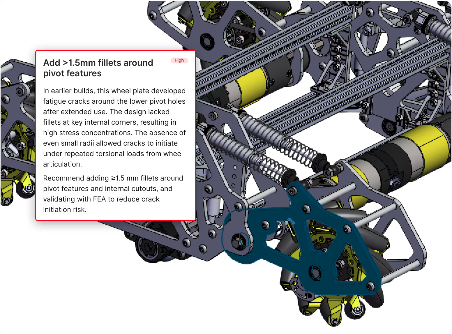
Radii and fillets deserve careful attention. Sharp internal corners at flow turns, ribs, bosses, snap roots, and cutouts concentrate stress and impede flow.
At the same time, overly generous fillets can unintentionally create thick “bulbs” of material at intersections. The goal is smooth, intentional transitions—not sharp stress risers and not disguised mass.
Features that frequently cause molding defects
Once the fundamentals are sound, attention turns to specific features that disproportionately cause defects in molded parts.
Ribs must be evaluated in context, not isolation. Their thickness relative to the adjacent wall, their height and spacing, and the quality of their root fillets all matter.
Ribs that are too thick telegraph sink and read‑through; ribs that are too thin risk short shots or structural weakness. Intersections—especially plus‑shaped rib crossings—are common sources of excessive mass and warpage.
Bosses, particularly screw bosses, are another frequent failure point. The thickness of the boss base, how it ties into surrounding walls, and whether it is properly cored or gusseted all influence sink and cracking risk.
Boss design must also reflect assembly reality: the assumed screw type, the presence or absence of inserts, and access for drivers. Many cracked housings trace back to boss designs that looked fine in CAD but were never validated against real assembly loads.
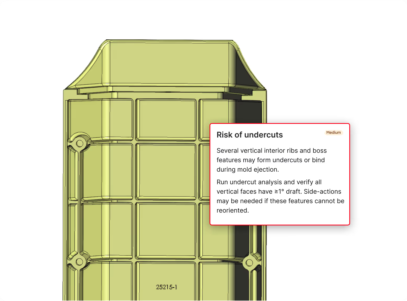
Undercuts and side actions require deliberate decisions. All undercuts—including small ones created by fillets, text, or latch geometry—should be identified.
The engineer must then confirm whether side actions, lifters, collapsible cores, or hand‑loaded inserts are intended and acceptable for the expected volume and cost. Accidental undercuts introduced by late ECOs are especially dangerous because they often go unnoticed until tooling review.
Parting lines and shutoffs reflect the physical reality of tool steel. Where the parting line runs relative to critical faces, seals, cosmetics, and functional interfaces has lasting consequences. Thin steel conditions at shutoffs increase tool fragility, while parting lines across sensitive features increase flash risk. These decisions are effectively permanent once the tool is built.
Knit and weld lines should be anticipated, even without full moldflow. Geometry that forces flow fronts to meet—holes, windows, bosses, and multiple gates—creates weld lines. When those lines land in high‑stress regions like snap roots or fastener bosses, or on cosmetic A‑surfaces, risk rises sharply.
Tooling and process‑driven checks engineers often miss
Some of the most painful injection molding problems arise not from bad geometry, but from unexamined process assumptions.
Gate location and gate vestige should be considered early. Every part needs a realistic place for a gate and its vestige—ideally somewhere non‑cosmetic and non‑functional.
Engineers should also look for regions prone to hesitant fill, such as thin ribs far from the gate or long flow lengths with trapped air. If the only viable gate location is on an A‑surface, that decision should be intentional, not accidental.
Ejection strategy is another common blind spot. Parts need robust regions where ejector pins can push without damaging thin ribs, delicate snaps, optical surfaces, or seals. Deep cores and insufficient draft increase the risk of parts sticking, distortion during ejection, and cosmetic damage.
Shrinkage and dimensional control bridge geometry and documentation. Critical interfaces must be dimensioned and toleranced with molding variability in mind. Datum schemes should make sense for molded parts, avoiding over‑constraint on cosmetic or freeform faces.
If post‑mold machining is required, it must be clearly defined, including stock allowance and datum targets. Unrealistic tolerances drive endless tooling “chase.”
Material choice and conditioning close the loop. Material callouts should specify exact resin grades rather than vague families or vendor‑specific shorthand. Fiber‑filled materials bring implications for warpage, surface appearance, abrasion, and minimum radii. Moisture‑sensitive resins require conditioning notes to avoid performance variation.
Drawing‑specific injection molding checks that still matter
Even perfect CAD cannot compensate for an ambiguous drawing. Missing tolerances, incomplete dimensional definitions, or unclear inspection intent leave manufacturing and quality teams guessing. Consistency across title blocks, callouts, notes, and the BOM is critical. A good drawing clearly communicates what is critical, how it will be measured, and what variation is acceptable.
The right way to think about AI in DFM
AI is not the mold designer and it is not the decision‑maker. It is a peer checker that catches injection molding DFM issues before they slip through the cracks.
When AI handles this part of design reviews, engineers are free to focus on what truly requires judgment: trade‑offs, collaboration with tooling partners and designing parts that succeed the first time they reach production.
If you’d like to learn more about AI agents in DFM workflows, schedule a call with us here.


About the author
Mary Keough is a real human and writer for CoLab. Email her at marykeough@colabsoftware.com.
